|
Polycarbonate housing having UL 94 V-0
All Rishabh meters are housed in robust case with classical finish. The case is made of polycarbonate, which is flame retardant and non-drip and confirms to international regulations UL 94 V-0. Polycarbonate is a very tough and light weight engineering plastic material which has got the best mechanical properties very close to a metallic housing. It is 10% glass filled, glass fibers give it extra toughness.
Application
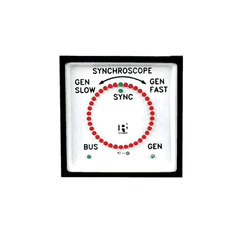
The electronic Synchroscope is designed to provide an illuminated indication of actual phase difference between the BUS voltage (reference voltage) & the GENERATOR voltage (incoming voltage).
It denotes the actual frequency difference corresponding to the inverse of time taken for one rotation of the illuminated vector spot. When two alternators are paralleled, it is necessary that Voltage magnitude, frequency and phase must be same.
Synchroscope is hence used to indicate the Phase & Frequency difference between two AC alternators, which are to be paralleled.
Synchroscope working
The rotation of the vector spot is with reference to the Bus voltage. If the vector spot LED turns clockwise, it indicates the GEN frequency is greater than the BUS frequency. It means the speed of the generator must be reduced by the operator.
If the spot LED turns anticlockwise, the GEN frequency is less than the BUS frequency. In this case, speed of the generator must be increased.
If ‘T’ is the time taken for one rotation, the frequency difference can be calculated as 1/T = Af
Example : Let the bus frequency be 50Hz. The vector spot takes 10 seconds for one clockwise rotation. 1/10 = 0.1Hz.
The frequency difference = 0.1Hz. Hence we can infer that GEN frequency is 50.1Hz.
If the Frequency & Phase of BUS signal matches with those of GEN signal, the two green LEDs at 12 o’clock position glow. If the frequency matches & phase does not, then one red LED corresponding to the phase difference will glow.
Favourable condition for ‘Switching in’ the Generator
* Ensure that the frequency difference between two inputs is within the requirements of user as follows: Measure time taken for one complete rotation of the vector spot in SECOND (T).
The frequency difference will be Af = 1/T (Hz)
* Provided the frequency difference is within acceptable limits, wait till the SYNC mark LEDs (two green LEDs at 12 o’clock position) glow. At this instant, it is safe to connect the GEN to BUS.
Terminal screws and clamps
Self lifting terminal screws are connected to the terminal clamps. Self lifted clamps gets lifted with the terminal screw while unscrewing, this simplifies clamping of the connectors or wire and save the time.
Terminal protection with click-fitting back cover
All Rishabh meters are supplied with a self-clicking back cover which covers the terminals. This is very important feature especially for the voltmeter because these meters are usually connected on the front panel which can be opened and can be hazardous for the engineer while the maintenance of the panel is being done. The self-click avoids problems of loosing the screws and washers.
Mounting arrangement
The meter has a unique swivel clamp which could be mounted in any of the two different positions at 90 deg to each other. This makes the meter suitable for grid-racking so that a number of meters can be mounted horizontally or vertically in one rectangular cut-out. This feature is also useful because making one rectangular cut-out is more economical than making several cut-outs. The design of the housing and swivel is such that it can accommodate any panel thickness from 1mm to 40mm.
Easy replacement of glass and bezel
Easy replacement of glass and bezel is possible in Rishabh meters at customer end without any tool. The glass with zero knob and bezel are click fitted in the meter.
|